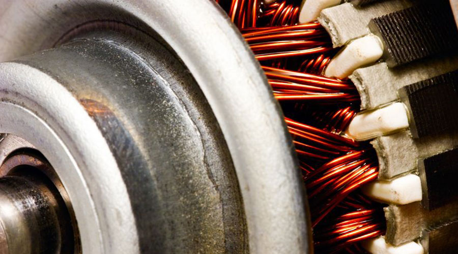
Energy efficient motors
Best Available Technique (BAT)
BAT is to increase the power factor according to the requirements of the local electricity distributor.
Brief technical description
Many electrical devices have inductive loads. These all require both active electrical power and reactive electrical power. The active electrical power is converted into useful mechanical power, while the reactive electrical power is used to maintain the device’s magnetic fields. This reactive electrical power is transferred periodically in bot h directions between t he generator and the load (at the same frequency as the supply). Capacitor banks and buried cables also take reactive energy.
Vector addition of the real (active) electrical power and the reactive electrical power gives the apparent power. Power generation utilities and network operators must make this apparent power a vailable and transmit it. This means that generators, transformers, power lines, switchgear, et c. must be sized for greater power ratings than if the oad only drew active electrical power.
Power supply utilities (both on-site and off-site) are faced with extra expenditure for equipment and additional power losses. External suppliers, therefore, make additional charges for reactive power if this exceeds a certain threshold. Usually, a certain target power factor of cost of between 1.0 and 0.9 (lagging) is s pecified, at which point the reactive energy requirement is significantly reduced.
(Electrical) power factor = Real power/Apparent power
For example, using the power triangle, if:
- real power = 100 kW and apparent power = 142 kVAr
- then the power factor = 100/142 = 0.70.
This indicates that only 70 % of the current provided by the electrical utility is being used to produce useful work.
If the power factor is corrected, for example by installing a capacitor at the load, this totally or partially eliminates the reactive power draw at the power supply company. Power factor correction is at its most effective when it is physically near to the load and uses state-of-the-art technology.
The power factor can change over time so needs to be checked periodically (depending on site and usage, and these checks can be anything from 3 to 10 years apart), as the type of equipment and the supplies listed (above) change over time. Also, as capacitors used to correct the power factor deteriorate with time, these also require periodic testing (most easily carried out by checking if the capacitors are getting warm in operation).
Other measures to take is:
- to minimise operation of idling or lightly loaded motors
- to avoid operation of equipment above its rated voltage
- to replace standard motors as they burn out with energy efficient motors
- even with energy efficient motors, however, the power factor is significantly affected by variations in load. A motor must be operated near of a high power factor design
Achieved environmental benefits
Energy savings to both the supply side and the consumer.
Across the EU as a whole, it has been estimated that if a power correction factor for industry was applied, then 31 TWh power could be saved, although part of this potential has been exploited. This is calculated on the basis that the EU-25’s total electricity consumption industry and service sectors in 2002 was 1788 TWh, from which industry used 65 %).
In an installation, it is estimated that if an operator with a power correction factor of 0.7 3 corrected the factor to 0.95, they would save 0.6 % of their power usage (0.73 is the estimated figure for industry and services).
Cross-media effects
None reported.
Operational data
An uncorrected power supply will cause power losses in an installation’s distribution system.
Voltage drops may occur as power losses increase. Excessive drops can cause overheating and premature failure of motors and other inductive equipment.
Applicability
At time of replacement
Economics
External suppliers may make additional charges for excessive reactive electrical power if the correction factor in the installation is less than 0.95.
Driving force for implementation
- power savings both inside the installation and in the external supply grid (where used)
- increase in internal electrical supply system capacity
- improved equipment reliability and reduced downtimes.
Example plants
Widely applied
 EE Metal


