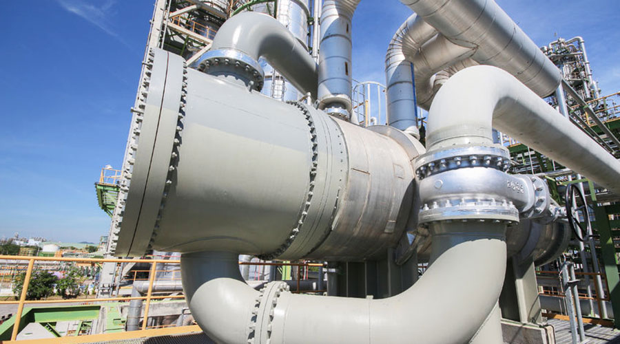
Heat exchangers
Best Available Technique (BAT)
BAT is to maintain the efficiency of heat exchangers by both:
- monitoring the efficiency periodically, and
- preventing or removing fouling
Brief technical description
Direct heat recovery is carried out by heat exchangers. A heat exchanger is a device in which energy is transferred from one fluid or gas to another across a solid surface. They are used to either heat up or cool down processes or systems. Heat transfer happens by both convection and conduction.
Heat exchangers are designed for specific energy optimised applications. The subsequent operation of heat exchangers under different or variable operating conditions is only possible within certain limits. This will result in changes to the transferred energy, the heat transfer coefficient (U-value) and the pressure drop of the medium.
The heat transfer coefficient and hence transferred power are influenced by the thermal conductivity as well as the surface condition and thickness of the heat transfer material. Suitable mechanical design and choice of materials can increase the efficiency of the heat exchanger.
Costs a nd mechanical stresses also play a major role in the choice of material and structural design.
The power transferred through the heat exchanger is heavily dependent on t he heat exchanger surface. The heat exchanger surface area may be increased using ribs ( e.g. ribbed tube heat exchangers, lamella heat exchangers). This is particularly useful in attaining low heat transfer coefficients (e.g. gas heat exchangers).
The accumulation of dirt on the heat exchanger surface will diminish the heat transfer. Dirt levels may be reduced by using appropriate materials (very smooth surfaces), structured shapes (e.g. s piral heat e xchangers) or changing the operating conditions (e.g. high fluid speeds). Furthermore, heat exchangers may be cleaned or fitted with automatic cleaning systems (dynamic or scrapped surface).
Higher flowrates will increase the heat transfer coefficient. However, increased flowrates will also result in higher pressure drops. High levels of flow turbulence improve heat transfer but result in an increased pressure drop. Turbulence may be generated by using s tamped heat exchanger plates or by fitting diverters.
The transferred power is also dependent on the physical state of the fluid (e.g. temperature and pressure). If air is used as the primary medium, it may be humidified prior to entering the heat exchanger. This improves the heat transfer.
Achieved environmental benefits
Energy savings are made by using secondary energy flows.
Cross-media effects
No data submitted.
Operational data
Condition monitoring of heat exchanger tubes may be carried out using eddy current inspection. This is often simulated through computational fluid dynamics (CFD). Infrared photography may also be used on the exterior of heat exchanges, to reveal significant temperature variations or hot spots.
Fouling can be a serious problem. Often, cooling waters from rivers, estuaries or a sea is used, and biological debris can enter and build layers. Another problem is scale, which is chemical deposit layers, such as calcium carbonate or magnesium carbonate. The process being cooled can also deposit scale, such as silica scale in alumina refineries.
- plate heat exchangers need to be cleaned periodically, by disassembling, cleaning and re-assembly
- tube heat exchangers can be cleaned by acid cleaning, bullet cleaning or hydrodrillling (the last two may be proprietary techniques)
- specific techniques are selected on a case-by-case basis.
Applicability
Heat recovery systems are widely used with good results in many industrial sectors and systems.
It is being applied for an increasing number of cases, and many of these can be found outside of the installation. Heat recovery is not applicable where there is no demand that matches the production curve.
Economics
Payback time may be as short as six months or as long as 50 years or more. In the Austrian pulp and paper industry, the payback time of the complex and different systems was between one and about three years.
The cost-benefits and payback (amortisation) periods can be calculated.
In some cases, particularly where the heat is used outside the installation, it may be possible to use funding from policy initiatives.
Driving force for implementation
- reduction of energy costs, reduction of emissions and the of ten rapid r eturn of investments
- improved process operation, e.g. reduction of surface contamination (in scrapped surface systems), improvement of existing equipment/flows, reduction in system pressure drop (which increases the potential maximum plant throughput)
- savings in effluent charges.
Example plants
Acid cleaning: Eurallumina, Portovecompany, Italy
 EE Metal


